Embark on a journey into the realm of electrical engineering with Lesson 3: Comprehending and Analyzing Series RLC Circuits. This chapter delves into the intricacies of series RLC circuits, unraveling their components, behavior, and practical applications. Get ready to expand your knowledge and master the analysis of these essential circuits.
In this lesson, we will explore the fundamental concepts of impedance and resonance, delve into transient analysis techniques, and uncover the power and energy dynamics within series RLC circuits. Armed with phasor analysis, we will navigate the complexities of AC signals and delve into the practical applications that make these circuits indispensable in various industries.
Series RLC Circuits: An Overview
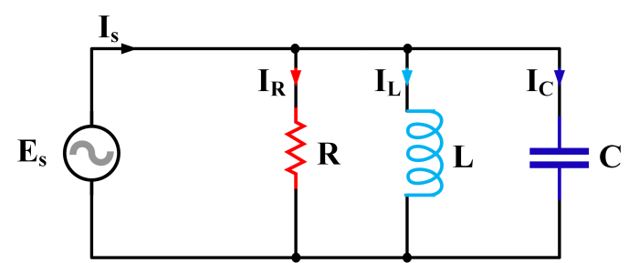
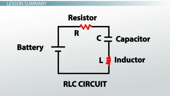
Series RLC circuits consist of a resistor (R), an inductor (L), and a capacitor (C) connected in series. These circuits are used in a wide range of applications, including filtering, tuning, and power systems. The basic components of a series RLC circuit and their functions are as follows:
- Resistor (R): Resists the flow of current and dissipates power in the form of heat.
- Inductor (L): Stores energy in a magnetic field and opposes changes in current.
- Capacitor (C): Stores energy in an electric field and opposes changes in voltage.
Circuit Analysis: Impedance and Resonance
Impedance is a measure of the opposition to the flow of alternating current (AC) in a circuit. In series RLC circuits, impedance is determined by the resistance, inductance, and capacitance of the circuit. Resonance occurs when the inductive reactance of the inductor and the capacitive reactance of the capacitor cancel each other out, resulting in a maximum flow of current.
Formulas and Equations
- Impedance (Z): Z = √(R^2 + (XL – XC)^2)
- Resonant frequency (f0): f0 = 1 / (2π√LC)
Transient Analysis: Step and Impulse Responses: Lesson 3: Comprehending And Analyzing Series Rlc Circuits
Transient analysis is used to study the behavior of a circuit when it is subjected to a sudden change in voltage or current. In series RLC circuits, the step response is the response to a sudden change in voltage, while the impulse response is the response to a sudden change in current.
Graphical Representations, Lesson 3: comprehending and analyzing series rlc circuits
The step response of a series RLC circuit is a curve that shows the voltage or current across the circuit as a function of time. The impulse response is a curve that shows the derivative of the voltage or current across the circuit as a function of time.
Phasor Analysis: Representing AC Signals
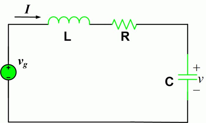
Phasors are a graphical representation of AC signals that allows for easy analysis of circuit behavior. In series RLC circuits, phasors are used to represent the voltage and current across the circuit.
Examples of Phasor Diagrams
Phasor diagrams can be used to show the phase relationship between the voltage and current in a series RLC circuit. The phase relationship depends on the frequency of the AC signal and the values of the resistance, inductance, and capacitance.
Power and Energy in Series RLC Circuits
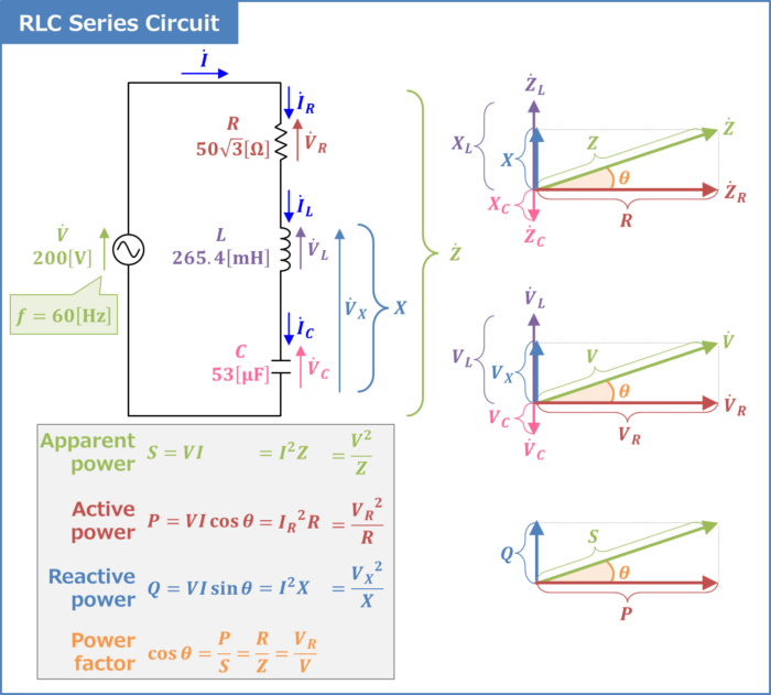
Power is the rate at which energy is transferred or consumed in a circuit. In series RLC circuits, power is dissipated in the resistor and stored in the inductor and capacitor.
Formulas and Equations
- Power (P): P = VI
- Energy stored in the inductor (WL): WL = 1/2 LI^2
- Energy stored in the capacitor (WC): WC = 1/2 CV^2
Applications of Series RLC Circuits
Series RLC circuits are used in a wide range of applications, including:
- Filtering: Series RLC circuits can be used to filter out unwanted frequencies from a signal.
- Tuning: Series RLC circuits can be used to tune circuits to a specific frequency.
- Power systems: Series RLC circuits are used in power systems to regulate voltage and current.
Query Resolution
What is the significance of resonance in series RLC circuits?
Resonance occurs when the inductive and capacitive reactances cancel each other out, resulting in maximum current flow and energy transfer. This phenomenon is crucial in applications like frequency tuning and filtering.
How does transient analysis help in understanding series RLC circuits?
Transient analysis provides insights into the behavior of circuits during sudden changes in voltage or current. It helps determine how a circuit responds to external disturbances and ensures stable operation.
What are the advantages of using phasors in series RLC circuit analysis?
Phasors simplify the analysis of AC signals by representing them as rotating vectors. This graphical approach allows for easy calculation of voltage, current, and power relationships in complex circuits.
